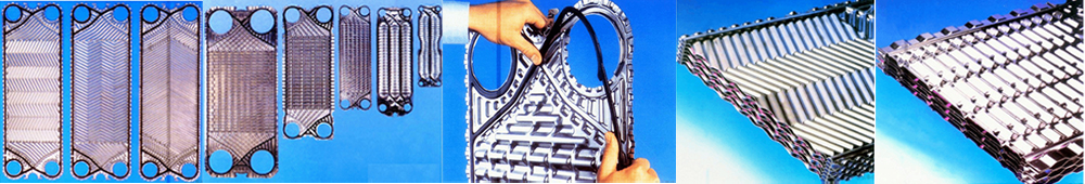
A flat plate heat exchanger is composed of a set of rectangular thin metal plates arranged in parallel, and tightly assembled on the bracket. The edges of the two neighboring plates are lined with the thickness of the gasket to regulate the size of the channel.
A pair of circular holes connects a group of inter-plate flow channels. The other pair of circular holes prevents fluid from entering the group of inter-plate channels by placing gaskets around the holes.
The positions of these two pairs of holes are staggered on adjacent plates to form separate channels for the two fluids.
Hot and cold fluids flow staggered on either side of the plates and heat transfer occurs through the plates.
The plates have a thickness of about 0.5 to 3 mm and are usually pressed into a concave-convex corrugated shape.
Herringbone corrugated plate.
It could increase the rigidity of the plate to prevent deformation when the plate is pressurized, and make the fluid distribution uniform simultaneously, as well as enhance the degree of fluid turbulence and increase the heat transfer conduction and area.
ᆞAdvantages:
High heat transfer coefficient:
Due to ripples or grooves in the plate surface, it can achieve turbulence at the low Reynolds number (Re = 200 or so). Besides the small thickness of plate thickness, the heat transfer coefficient is large.
For example, the water-to-water heat transfer coefficient is up to 1500 ~ 4700W / (m2.℃).
Compact structure:
General plate spacing is 4 ~ 6mm, The heat transfer surface that can be provided by unit volume equipment is 250 ~ 1000m2/m3 (tubular heat exchanger is only 40 ~ 150 m²/m3). The flat plate heat exchanger saves 50% of metal consumption.
With removable structure:
The number of plates is adjustable to increase or decrease the heat transfer area.
The operation is flexible.
Easy for overhaul and cleaning.
ᆞDisadvantages:
Allowable operating pressure and temperature are relatively low, usually less than 1.5Mpa. The maximum does not exceed 2.0Mpa. Because high pressure is easy to cause leaking.
The operating temperature is limited by the heat resistance of the gasket material and generally does not exceed 250 C. In addition, due to the distance between the two plates being only a few millimeters, the circulation area is small, the flow rate is not large, and the processing capacity is small.
Both spiral plate heat exchangers and flat plate heat exchangers have features of compact structure, low material consumption, and large heat transfer coefficient. They belong to the new high-efficiency compact heat exchangers.
They could not be used at high temperatures and high-pressure conditions.
But for the conditions of lower pressure, low temperature, or highly corrosive expensive materials, they show greater superiority.
They have been widely used in the food, light industry, and chemical industries at present.
2.3.2.3 Plate shell heat exchanger ( PSHE)
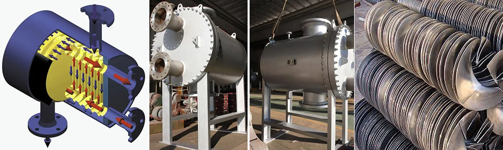
ᆞAdvantages:
Close arrangement, compact structure, high heat transfer coefficient.
The heat exchange surface provided per unit volume is more than 3.5 times compared with the tubular type exchanger.
The sturdy structure can withstand high pressure and temperature.
Compact structure.
Heat transfer area per unit volume is 70% more than tube-shell exchanger.
High heat transfer efficiency and small pressure drop.
Compared with a flat plate heat exchanger, it provides a better solution to the contradiction between temperature resistance, pressure resistance, and high efficiency because it doesn't need a sealing gasket.
Easy to clean.
Commonly used in heating, cooling, evaporation, condensation, and other processes.
ᆞDisadvantage:
High welding technology requirements.
2.3.2.4 Jacketed heat exchangers
ᆞDescription:
The jacketed heat exchanger type is the simplest plate heat exchanger, which is made by installing a jacket on the external wall of the vessel, and the space formed between the jacket and the vessel is the pathway for the heating medium or cooling medium.
This type of heat exchanger is mainly used for the heating or cooling of the reaction process.
When heating with steam, the steam enters the jacket from the upper receiver and the condensate from the lower port.
When it is used as a cooler, the refrigerant medium (e.g. cooling water) enters into the lower receiver of the jacket and exits via the upper port.
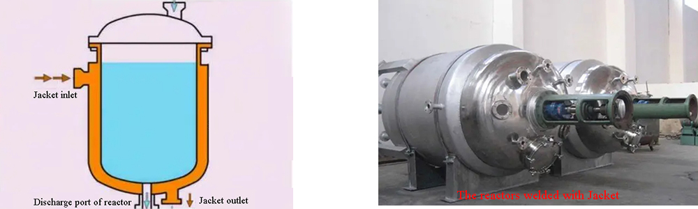
ᆞAdvantages:
Simplest structure.
It can be welded together with the reactor and occupies little space.
ᆞDisadvantages:
The heating surface is limited by the vessel.
The heat transfer coefficient is not high.
ᆞApplication:
To improve the heat transfer coefficient, a stirrer can be installed inside the vessel. The coil pipe can be installed inside the vessel to support the heat transfer surface.
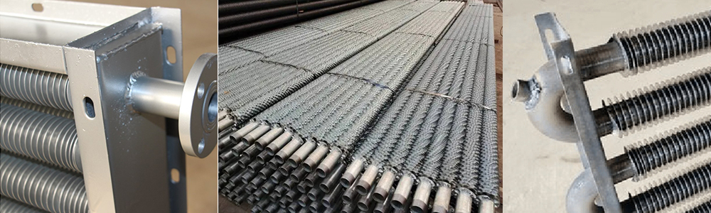
2.3.3 Finned Heat Exchangers
2.3.3.1 Finned tube heat exchanger
ᆞDescription:
The tube of the exchanger has fins added on. The connection between the fins and the tube surface is tight and seamless to provide good heat transfer.
Fins connection methods:
Heat sleeve, inlay clamp, tension winding, and welding. In addition, it can also use overall rolling, overall casting, or machining methods.
ᆞAdvantages:
When the difference in convective heat transfer coefficients between the two fluids is large, adding fins on the side with the smaller heat transfer coefficient can enhance heat transfer.
For example:
Heating air with water vapor.
The main thermal resistance of the process is the convective heat transfer thermal resistance on the air side. Adding fins on the air side can enhance the heat transfer.
ᆞDisadvantages:
Adding fins will increase the equipment cost.
However, when the ratio of the convective heat transfer coefficients of the two fluids exceeds 3:1, the application of fins is economical.
ᆞApplications:
In recent years the air cooler made of finned tubes has been widely used in the chemical industry. Using air cooling instead of water cooling is not only applicable in water-scarce areas but also in places with sufficient water sources, the use of air cooling can also achieve greater economic results.
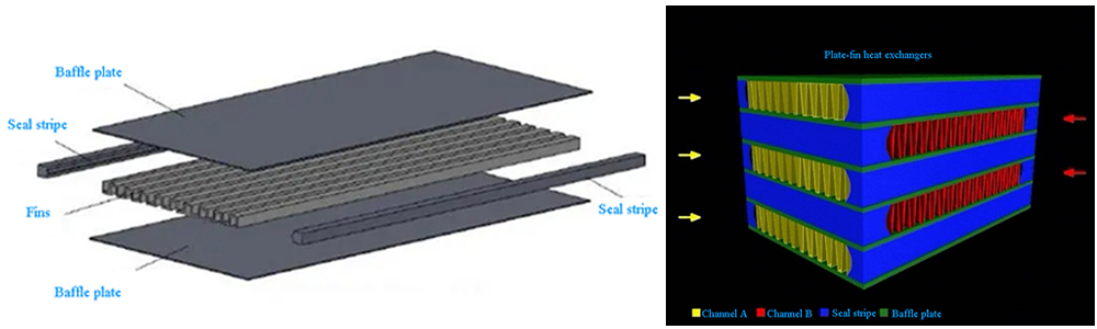
2.3.3.2 Plate-fin heat exchangers
ᆞDescription:
The plate-fin heat exchanger is a more efficient, compact, and lightweight heat exchanger.
Structure:
There are many structural forms of plate-fin heat exchanger, but the basic structural elements are the same, i.e., between two parallel thin metal plates, corrugated or other shaped metal fins are added, and seal the two sides, which becomes a basic element of heat exchange.
ᆞProduce process:
To make a plate bundle, need appropriate stacking and arrangement for the basic elements, and fix them by brazing. The plate bundle (or core) supports parallel flow, countercurrent, or staggered flow.
Weld the collector box with the fluid import and export ports to the plate bundle.
Type:
Glossy straight fins exchanger, serrated fins exchanger, and multi-hole fins exchanger.
ᆞAdvantages.
High thermal efficiency:
The heat transfer coefficient is 3 to 10 times greater than that of shell and tube heat exchangers.
Higher heat transfer coefficient due to the fins promoting fluid turbulence and destroying the development of the thermal boundary layer.
The heat transfer surface provided by the unit volume equipment can generally reach 2500~4370 m2/m3 (1000x6000, 347m2, 74m2/m3 in tube-shell exchanger).
Unit weight heat transfer area is large:
Its area is ten times to dozens of times more than a tube-shell exchanger.
It is usually made of aluminum alloy, so the weight is light. Its weight is only one-tenth of the tubular exchanger with the same heat transfer area.
Wide adaptability:
Can be used for gas-gas, gas-liquid, and liquid-liquid heat exchange.
Can also be used for condensation and evaporation.
It applies to a variety of different fluids operating in the same equipment.
It can be used for 0 ~ 1000K range of heat exchanging if selecting appropriate materials.
Aluminum alloy not only has high thermal conductivity, but also has high ductility and tensile strength when operated below zero degrees, which is suitable for low and ultra-low temperature occasions, so it has a wide operating range. It can be used in the range of 200℃ to absolute zero degrees.
High operating pressure:
Because the fins have a supporting effect on the spacer, the allowable operating pressure of the plate-fin heat exchanger can be 5MPa.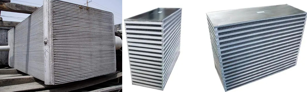
ᆞDisadvantages:
Complex structure, high cost.
The equipment flow channel is very small and easy to clog.
Cleaning and maintenance are difficult, so the materials handled should be cleaner or a pre-purification system.
The fins of the partition are made of thin aluminum plates, so the medium can not corrode aluminum.
Application:
Because of the high cost of manufacturing, it was used only in aerospace, electronics, atomic energy, and other minority sectors. However, it has been gradually used in petrochemical and other industrial sectors in recent years.
2.3.4 Heat pipes
ᆞDescription:
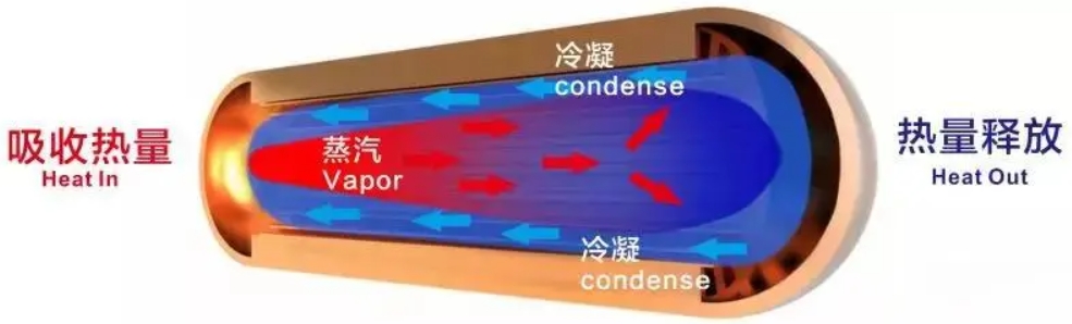
Heat pipes are a new type of heat transfer element developed in the mid-1960s. It is a sealed metal tube filled with a certain amount of certain working liquid after the tube is filled then vacuumed with non-condensable gas.
Principle of operation:
The working liquid absorbs heat, boiling, and vaporing at the hot end. The steam flows to the cold end, condenses, and releases the heat. The condensed liquid is back to the hot end and reboil. The heat is constantly transferred from the hot end to the cold end as the cycle repeats.
ᆞTypes:
The reflux of condensate can be realized by different methods:
Capillary action, gravity, centrifugal force.
The most widely used method is capillary action. It is to install the suction core with a capillary structure on the inner wall of the tube. By the capillary effect, condensate reflux from the cold end to the hot end.
Working liquids:
Ammonia, water, mercury, etc..
ᆞAdvantages:
Heat pipes can be used over a wide range of temperatures.
Heat transfer of heat pipe is in three steps: boiling vaporization, steam flow, and steam condensation. The boiling and condensation of convection heat transfer intensity are large, and the cross-section of the tube surface at both ends is much larger than the cross-section of the tube. The resistance loss of steam flow is small. So the heat pipe at both ends of the temperature difference can be very small, that is, it can transfer a large amount of heat flow at a very small temperature difference.
Compared with the metal wall of the same cross-section of the heat pipe, the heat pipe's thermal conductivity can be up to 103 to 104 times the best metal heat conductor. Therefore, it is particularly suitable for occasions with small temperature differences as well as occasions with high requirements for isothermal properties.
The heat pipe of this heat transfer characteristics for the device (or room) inside and outside the heat transfer enhancement provides a very favorable means.
For example.
Both sides of the device are gases.
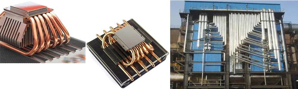
By installing a heat pipe on the wall of the device, increasing the length of the ends of the heat pipe, and adding fins to the pipe, you can greatly accelerate the heat transfer inside and outside the gas pedal.
In addition, the heat pipe also has the advantages of a simple structure, long service life, reliable operation, and a wide range of applications.
ᆞApplications:
Heat pipes were initially used in the aerospace and electronics industries. In recent years, they have achieved good results in the utilization of industrial waste heat.
2.4 Classification by material:
2.4.1 Metal materials heat exchanger
Steel, copper, aluminum and their alloy, Titanium, Zirconium, Tantalum, Inconel, etc.
2.4.2 Non-metallic materials heat exchanger.
Graphite, glass, plastics, SiC, ceramics, etc.
III, Heat exchanger cleaning
3.1 Heat exchanger cleaning reasons
After a period of operation, there would be a layer of white scale on the inside and outside the wall of the heat exchanger.
3.1.1 Thermal conductivity of scale is very poor
The heat exchanging efficiency will drop about 10% when there is a 1mm thick scale.
3.1.2 The scale can cause equipment failure.
It will reduce the heat transfer surface circulation, increase water circulation resistance, reduce the cross-section area, and even block the flow.
3.2 Cleaning method of heat exchanger
3.2.1 Dosing softening treatment
The method is simple with high efficiency, good economy, and does not require special water production equipment.
Types:
Correction agent treatment.
Anti-foulant treatment.
3.2.2 Ion scale inhibitor
Ion anti-scaling treatment is a new, advanced water treatment equipment for the hot water circulation system, central air conditioning system, and circulating cooling water system. It achieved satisfactory results for the heat exchangers.
3.2.3 Magnetization anti-scaling treatment
Magnetization anti-scaling treatment principle is the use of water molecules, with the polarity of the water molecules combined.
When the fluid is through the high-intensity magnetic field, the multi-molecule associations in the water act with the ion's magnetic field.
The original single scattered multi-ion associations are disassembled into single or short bond associations. They cut the magnetic lines of the external magnetic field with a certain speed perpendicularly and produce an induced current.
Therefore, each ion and the external magnetic field establish a new field, established in the adjacent polar ions, ordered, mutual attraction compression, the formation of the change in conditions, resulting in changes in crystallization, the formation of crystalline material is very flaccid, compressive strength, tensile strength is poor and is very brittle, cohesion and adhesion is very weak.
So they are not easy to attach to the heated surfaces on the formation of scale.
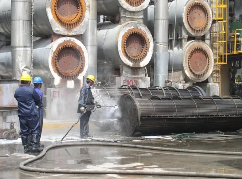
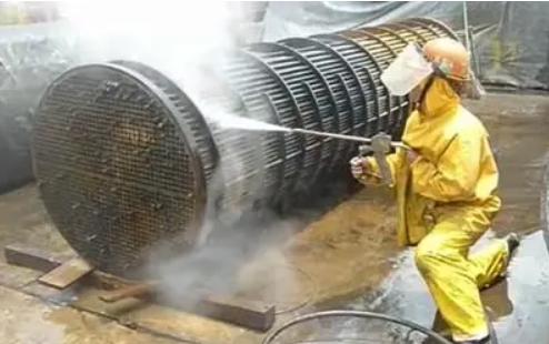
3.2.4 High-pressure water flushing method
The high-pressure water flushing method is mostly used for cleaning the tube bundles with serious coking, such as catalytic slurry heat exchangers.
3.2.5 Sponge ball cleaning method
Put the soft and flexible sponge ball into the tube, and press the sponge ball to make it in contact with the inner wall of the tube. Then manually or mechanically push the sponge ball along the tube wall, and constantly rub the tube wall, so to remove the scale.
3.2.6 Mechanical cleaning method
For serious scaling and clogging, use a tube impact drill to unclog and clean.


